
Quick Answer
Include a controlled 2D drawing and 3D model, hole and cutout locations, size and tolerance, panel thickness, hardware callouts, cable-entry components, internal clearance and any sealing requirement. Show the view and datum from which each location is measured. If the cable gland, connector or bracket is not selected yet, mark it as an open decision rather than issuing an incomplete dimension as final.
Factory Scenario: The Cutout Is Correct, but the Connector Still Does Not Fit
In an illustrative enclosure review, a rectangular panel cutout may match its drawing while a connector body collides with a nearby flange after bending. Another risk is locating a cable opening from an edge that changes during forming, while the equipment designer intended alignment with an internal rail. The issue may be a mismatch among the dimension reference, formed geometry and installed component envelope, not the cutting operation.
Before release, overlay the connector, gland, bend line, flange and interior clearance in one view. The buyer confirms the intended arrangement. This is a design-review example, not a claim of a specific production failure at Nbfeiyu.
Define the Interface, Not Just the Hole
Identify the component passing through
Give the supplier the gland, connector, conduit fitting or cable assembly part number and datasheet when available. A nominal thread callout may not describe wrench clearance, body diameter, sealing washer or engagement. If the enclosure maker is to source hardware, identify acceptable requirements and ask the quote to list the exact proposed component for approval.
Locate openings from functional datums
Dimension centers or edges from surfaces that remain meaningful after forming and assembly. Avoid relying only on a free edge if the opening must align with an internal plate, neighboring panel or mating machine. State whether dimensions apply before or after coating when finish buildup could affect fit. For patterns, use a baseline or coordinate scheme instead of chains that accumulate tolerances.
Show the cable path and service access
Consider bend radius, strain relief, connector insertion direction, tool access and room for a technician’s hand. Show the interior components and likely route, not only the exterior opening. Confirm the installed orientation. A drain or vent may also affect protection, so the equipment specification should define it.
Connect mounting features to the installed load
Identify wall brackets, feet, rails, standoffs or mounting plates and indicate the installation datum. Define fastener size, access direction and captive hardware. For a heavy assembly or vibrating application, engineering should state the load and mounting condition for review. Do not infer load capacity from a photograph or nominal sheet thickness.
Check the Build Sequence
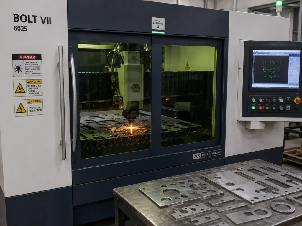
Cutouts can be laser cut or punched in a flat blank, then the panel is bent, welded, coated and assembled. Each step can change access or fit. A hole near a bend may distort during forming; a welded frame can shift mounting points; coating may affect threads or close-fitting hardware. Nbfeiyu’s sheet-metal enclosure case describes cutting, bending, welding, powder coating and final assembly, with review of hole patterns, door fit and coating before packing.
When cable entry is part of an ingress-protection requirement, define the target and test configuration separately. Agree whether acceptance evidence applies to the bare enclosure or complete assembly with selected glands and plugs. The electrical and telecom components page lists enclosures, cabinets and mounting structures among its custom component work.
Drawing and Inspection Notes Buyers Should Agree
Mark critical interface dimensions and what constitutes a functional failure. Record hole position, panel thickness, mounting flatness or clearance when these affect assembly. Choose a measurement method that can access the feature. The quality-control system describes selecting inspection methods against drawing tolerances and project requirements. For multi-part enclosures, mechanical assembly capability is relevant when glands, hinges, fasteners or panels are assembled together.
Keep a single revision across the 2D drawing, 3D model, connector specification and bill of materials. If a component changes, route it for fit and sealing review before the next production order. Use the RFQ checklist to make sure the quote package includes the information needed for review.
Buyer Checklist
- Attach 2D and 3D files with matching revision identifiers.
- Provide connector, gland or fitting specifications and exact model when selected.
- Locate openings and mounting points from functional datums; identify post-finish dimensions where needed.
- Show bends, flanges, internal plates, cable route and tool/service clearance.
- Define panel thickness, material, finish, masking and grounding requirements through engineering.
- State the ingress or environmental target and whether validation applies to the complete assembly.
- Mark critical dimensions, acceptance criteria, sample approval steps and records required before production.
FAQ
Can I send only a 3D model?
A model helps visualize the design, but a controlled 2D drawing should identify tolerances, datums, material, finish and acceptance requirements. Do not assume the factory will derive unspecified requirements.
Who selects the cable gland?
The equipment designer should define the electrical, environmental and installation requirement. The manufacturer can quote a named part or propose an option for buyer approval.
Should cutouts be checked after coating?
That depends on whether the finished opening or bare-metal dimension controls fit. State the acceptance condition and whether the opening needs masking.
Conclusion
A well-defined interface drawing lets the factory review cutouts, bends, hardware and assembly as one design. Resolve connector choices and datums before production so a dimensionally correct panel also works in the installed product.
Need an Enclosure Interface Review?
Send the drawing, connector details, mounting condition, finish and target environment..